Tuesday 19 September 2017

Programming the Staging Yards:


Staging Yards.  ( BTW the German alphabet has no "Y")

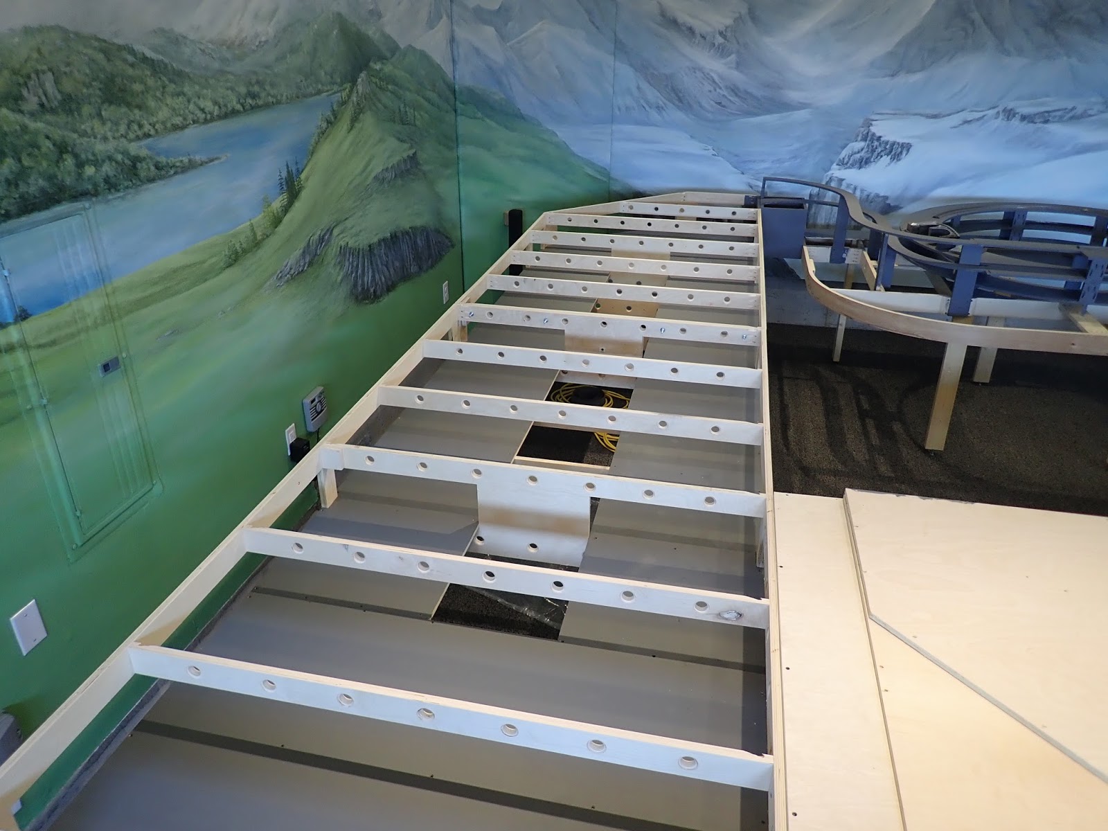
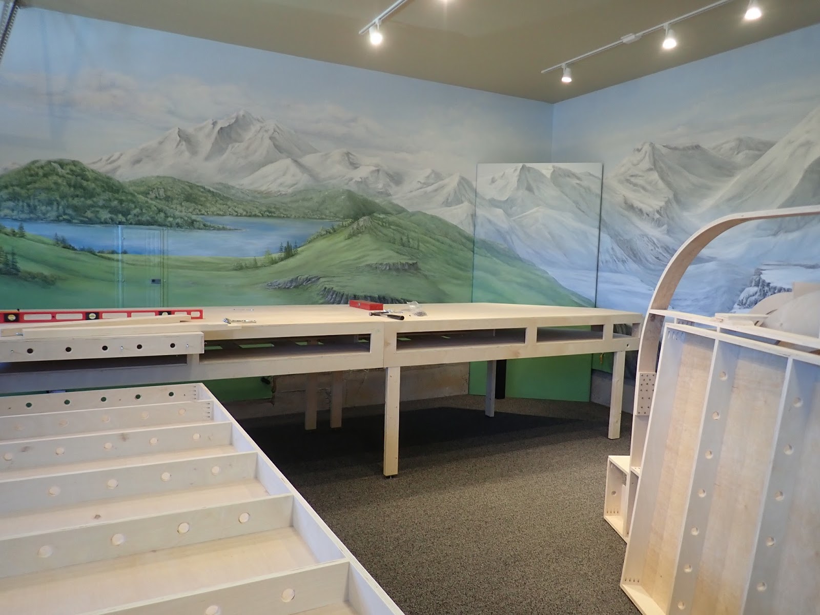
This is the "north bound" section of the yards, with an almost reciprocal image for the "south bound" lanes.  One passing lane and 4 "holding" lanes on each side of the staging area.

Conceptually, the plan follows thus: 
1) The passing lane ( entry / exit lane ) will not be automated.
2) The staging yards will be automated.
3) Entry into the Staging lanes will be manually controlled, not automated.  ( more below)

Stop Blocks:
Prepare a stop block at the end of each lane with M84, K84 or VM 5213.  Make certain that when the train halts it will not impinge on any other adjacent lanes.

Contact Tracks:
Much has been written about Contact Tracks. Best reference: Curtis' article in the Marklin Digital Newsletter: Vol 27, No. 2 pages 6 & 7.  Make certain that then CT's are not too long ( about one car length) otherwise the CT shortens the length of any train which can be stored on that lane.

Be careful! Contact Tracks are a trap for frustration. Some pointers:
1) Use a Dremel to cut the "ground" joints under "C" track--cleaner method.
2) Solder a single wire to the CT section. I chose "blue" wire for simplicity...to connect to the L88. NO solder on these connections to the L88!!!!
3) Keep meticulous notes! Keep meticulous notes!!!
4) In the layout mode place the CT icon on each lane and ID the contact point.
5) Frustration:  Even tho the CT's were properly soldered, and insulated on all lanes, ( I thought!) the icon on the layout panel of the CS 2 --on only ONE lane indicated occupancy when there was none! Now what?  After replacing track, and essentially rebuilding the CT area, the same occupancy indicator appeared!  Aarrrgh!  Then the "light" went on....the insulator points were on the same "ground" side of the track, but not on the proper side....switched the insulators to the other side. and hooray ...it worked.

I have not seen this mentioned in some of the other blogs I have read....just a word of caution! ;-)

Now onto programming the yards..........

Now for "fun" times!!??  The process is actually fairly straightforward IF you follow all the instructions precisely.  ( I made plenty of mistakes!)

References:  Marklin Digital Newsletter: Vol 28, No. 1; ( pages 6-12);  Vol 28, No. 2 ( pages 6-13)
Study them...a lot!

1) Make certain all the components are programmed into the "Keyboard": Turnouts, Stop Blocks and Contact Tracts
2) Make certain all the components of the layout are programed on the "Layout" section, including all  Turnouts, Stop Blocks, and Contact Tracks.
3) Programming the "Memory" section, involves "activating" ( wrench) the Memory Section while accessing the components in the Layout Section  ( not the Keyboard....much easier to use the Layout Section)

See pix below with explanation:

Goals: 
a)  Have a passing "main line" lane through both sides of the staging yards, with 4 storage lanes on each side of the yard.
b) This allows "favorite" trains to pass thru the staging yards and return via the helix to the main level of the layout.
c) Option of "manually" operating a turnout, allowing a train to enter the staging yards to an empty storage lane on either side of the yard.
d) Once the Turnout has been thrown allowing the train to Enter the Staging Lane ( SLn), the train passes over the Contact Track,  converting the Stop Track on the same lane to turn red...to stop, and also turns the adjacent stop track to "green", allowing that train to leave and enter the main through lane.
e) When the train Exits the contact track, the turnout through which the train entered the staging lane now turns to prevent another train from entering the same lane.

Screen shot of the Layout: one side of the staging lanes. A train has entered the lowest lane and stopped. Simultaneously, the train in the lane just above the lowest lane has left the yards, because the stop track has changed to "go", releasing that train.


2)Memory screen:
 Wrench->Note: 
Address: SLn5 ( Staging Lane 5) 
Contact: 5 
"Tr." Loco on the ENRTY or Lt side of small screen. ( Entry into the Contact Track area). 
Add ( Stop Tracks): "Stop" for Ln 5 and "Go" for Ln 6, by clicking on the specific component on the layout screen. ( only the Memory Screen is "active" for programming, not the Layout Screen. 


 Programming the "Exit" component from the Contract Track:--> Move the "Loco" icon to the right side of the little box with the pointer. Then, select the turnout from the Layout Screen. Thus when the train leaves the Contact area, the turnout throws to prevent another train from entering that same lane.


 Next step: Click on the "EXT" icon. This screen appears. The top line is the "temporary" contact line ( see Newsletter). Make certain that the appropriate contact track number is registered. e.g #5! AND the L( S88) is registered!!!!!   Close this screen. When finished programming that Memory icon, then close the window with the blue down arrow and then the green check mark. ...to save the info.


This screen shows a Loco entering the staging lane at the top of the four lower lanes. The very top lane is the "main line". The contact icon is yellow....indicating occupancy.   REMEMBER: if your Contact Track appears yellow and there is NO train on that CT, then you have your insulator points on the WRONG side of the track!  


Good luck programming your staging yards.  Full disclosure: this section drove me crazy for awhile, till I sought advice from others and re-read the Newsletters...for the ~10th + time! 
I believe that one of my biggest obstacles was the time frame involved for the Central Station to "digest" the programmed information. My "hunch" is that the processor in my older 60214 is much slower that the newer models. ( When finished programming any information, I usually allow the CS to remain "on" and "idle" for about a half hour before "saving" the information and then "quitting" the CS. 

It's most difficult not to become discouraged or frustrated. Persistence  is the key. Ask for help if needed. Some "figure it out" before others. I am writing this blog to try to help others avoid some of the frustrations that I encountered. 

Blessings....alan 


Addendum: 

Side point: I marked the insulation point on the track in the Staging Yards with a double black stripe, so if I have to return to shorten or lengthen contact blocks or stop blocks I would know immediately where the insulation points were located. 

Contact track: marked with an "X" where insulator points are located. 


Brief video showing how train passes over contact point and throws turnout to prevent another train from entering that particular staging lane. 


Friday 1 September 2017

Fisher Bahn II : Connecting the L88

Connecting the L88

For the most part connecting the L88, the first device between the CS and the S88 feedback module
network is easy following the instruction manual.


Ref:  Digital Newsletters: Vol 27: #2,   Vol 28: #1-2

Connect the L88 to the CS at the 60174 booster slot. All S88's then connect to the L88.  THEN connect the power module. 

Do not make the same mistake I made with my dual Central Stations! 

The red wire rising from the Left CS is a temporary programming wire connection to a section of track to register locos and reprogram signals. 

Problem: I mixed the connections between the "slave" and the "master" CS units and my L88 would not properly register on the master CS. ( thought I had really scoped out the correct connections!!) 

Further the checked boxes for the slave to acquire information from the master are actually located on the slave CS under the set up panel. 

In sum: The cable connecting the two CS's: the 6 pin connection is the master; the 9 pin connection is the slave.  Once properly connected, no problem with registering the L88.  

Whew...now onto the fascinating challenge of installing signals ( stop blocks), contact tracks for each staging lane, and programming the CS's so that when a train enters an empty staging lane, it released a train in an adjacent lane....should be fun when it all works out!!!! ;-) 


Fisher Bahn II Step 1: Automation of Staging Yards : Stop Blocks.


Programming Signals with the Central Station 2. 


Automation of the staging yards: Step 1:  Installation of "stop blocks"

1) The best Marlin references on the planet are the Digital Newsletters from the Marklin Digital Club!  Take a bow, Curtis Jeung, you are a hero to so many of us! 

2) Reference: Digital Newsletters, Vol #27:  No. 1-3 , and Vol # 28: No. 1-3

Because I retained 8 Marklin yard signals, 74371 / 76371, from my old layout, and because they really look cool when watching a train stop in the staging yards, I decided to wire them into the layout as an easy way to secure a stop block for each of the staging lanes. 


I happen to be one of those folks who needs specific instructions on how to wire or connect devices. 

To reprogram these signals I read the signal instructions, reviewed the newsletters, and decided to give it a shot. I had never used the CS to program signals before. (  CS = 60214- with current software: 4.2.1 ) 

Below is a concise summary: 

  • CS powered but turned OFF. 
  • Program Track: ( connected to Program Track slot of CS) 
    • Connect feeder wire paddles to track end  R / B 
    • Connect Yellow from signal to Red ( Brawa Plug set)
    • Connect Brn  from signal to Brn ( Brawa plug set) 
  • Connect "programming base" from original packaging to bottom of signal circuit board ( the cardboard panel that clips onto both sides of the circuit board) 
  • CS "ON"
  • Keyboard Mode: Select the Keyboard panel you wish to use. 
    • Choose the slot for the signal 
    • "Wrench" ->highlight the keyboard icon
      • Set address: e.g S 5
      • Select Icon: e.g. Sh0, Sh1 ( stop, go) 
      • red / white lights on signal should flash alternately. 
      • Close out programming mode. 
  • Remove programming base. 
  • Check signal. 
  • Your signal is now reprogrammed! 
Now, install them!  ;-) 

Addendum:  19 Sept:  Decided to save the signals for the most visible part of the layout, and not use them for the staging yards. Choices for control devices:  VM 5213,  M84, K84. All work quite well and are easy to install and program on the keyboard.  Enter the information onto the "layout" portion of the CS.  ( Marklin Digital Newsletter resource is invaluable!!!! )

Wiring for the Stop Blocks: 
1) Used "green" wire from the middle of the stop block to connect to the control module--fitting because the wire inserts into the "green" port!
2) Red wire to the outside of the stop block.
3) The group of staging lanes were insulated from the main line as expected.  Had to install another feeder wire to the "down" side of the stop block grouping for power.


Fisher Bahn II--Wiring Staging Yards,


Wiring Staging Yards. 

Keep thy wiring neat!

 I've read many posts about wiring, some are absolutely ingenious! I chose to follow the older system, using a larger caliber wire from the Transformer / Booster  combo to the distribution panels. Then connecting the feeder wires after soldering the tips, of course. 

FWIW I have been using a butane soldering iron which works well. Why, you ask?  


Two reasons:
1) While moving around under my last layout, and using a traditionally plug-in soldering iron,  I happened to accidentally place the palm of my hand on the soldering iron!!! Big ouch! Now when I am done with the short soldering chores, such as wire tips, I turn off the iron and place it in an old teflon coated pie pan and push it away!
2) While using the same traditional wire fed soldering iron, the dumb thing fell off its cradle and burned the rug! Ugly! My bad! 

------------------------------------

This time, I am meticulous to make certain that my red / brown wire junction plugs are not adjacent to each other but safely offset.   On my old layout,  two plugs contacted each other and shorted out the entire layout....what a mess to diagnose and finally resolve the issue!  Zip tags are an easy method to identify ( and record!!!) your wiring harness.  

Remember: Experience-> knowledge-> wisdom-> success.  By sharing blunders and faux pas perhaps we will spare others !  ;-)  


Previously, my wiring was almost all "overhead" secured to the underside of the lowest level of the layout.  A few scalp scars attest why this current layout's bottom level is higher than the last one! Further, I will never secure servers, etc overhead....especially with soldering...too much danger of solder accidents.


Now, I secure wiring harnessed to a vertical plane. This particular panel is screwed to a support leg of the layout.  Note that each bus is labeled with the Zip tags. 
Bus #1: Through lanes
Bus # 2: "South bound lanes
Bus #3 North bound lanes. 

<- N,  S->

Red dots: insulating points
Black dots: Feeder wires 
Yellow lane: Main through route. 

Keep meticulous notes !!!!

Fisher Bahn II --Staging Yards.

Staging Yards: 

Issues: 

1) Staging yard  will be intentionally visible by visitors.
2) Access to all lanes of traffic in case of derailments ( on my last layout this was eventually an unsolvable problem causing me to abandon the two lanes adjacent to a wall which were not accessible! )
3) Ability to monitor the staging lanes visibly: lighting and cameras.
4) Length of lanes: to accommodate consists of at least 7 passenger cars.
5) Automation of staging lanes.


                                              Top deck ( main level) removed to access the
                                              Staging yards. Main level 42" above ground.
                                              Staging yards 34" above ground.
Note the holes in the cross beams for 
wiring harnesses.  Bench work replete with these 
features.  
Note also a 12" spaces between each side of the 
Storage lanes, allowing access from beneath the
middle of the layout if necessary. Total width: 48"
Easy reach to all lanes from each side. 
Base of staging area painted gray. 
Laying track! Yippee! 
Lanes to and from the helix, also painted 
gray. 
Cameras from previous layout to spy on entry 
of trains into each side of the storage lanes. 

Camera View from small TV  
Woodland Scenics Foam track bed under C track. 
Easy to install and works perfectly to eliminate 
noise transmission to the base bench work! 
WS foam held up perfectly for me for over 14 years 
with previous layout ! 
Lighting!!!  LED rope lighting will illuminate 
the staging yards. In line Rheostat works perfectly
to adjust light intensity. 

BR 44 under the LED lights. 


Fisher Bahn II -- Benchwork.

Bench Work. 

As mentioned previously, limited time and expected longevity ( some of you know exactly what I mean!  ;-)  ) seem to dictate some degree of expediency in establishing a bench work platform.

After all, the grandkids and the neighborhood kids are anxious to see Papa's layout up and running soon!  The bench work of my last layout required about 1.5 years to build...albeit whilst I was still working..additionally, my carpentry knowledge and possession of necessary equipment seemed too limiting.

Thus I reached out OnDrew Hartigan at Model BenchWork:Modelrailroadbenchwork.com. I emailed my layout as designed on Railmodeller Pro ( there are lots of great programs, I just happened to choose this one, having used it before).

Within a few short weeks my layout was completed and shipped directly to my home.

                                         
                                            Bench work on pallet in driveway! Yippeee!!!!

Well anchored pallet....


Moving the modules into the garage. Zigi, the wonder
dachshund remains unperturbed! 

Assembling the modules. The distant module is the 
"vertical" module on the track plan, with the 
main level and the storage yards beneath. 

Progress!!! 

Moving the helix into position.. Helix is a master
piece of carpentry! Note the rounded base. 

Moving last module into place. This module will
be home for the Monastery, Church and the 'nur ein berg". 

Modules bolted together and leveled. Friends are 
priceless!  ;-)


Final assembly. Storage cabinets holdover from
last layout. Beautiful carpentry by a friend.  
Transformers and boosters to be located on the 
deck of the storage cabinets. 

Another view of the assembled layout. 
Assembly time: approx: 4.5 HOURS !!!! 

Fisher Bahn II Staging Yards.


Staging Yards: 

1) Single main line ..through route
2) Storage lanes = 8. 
3) Plan to automate storage lanes
4) Lanes long enough to easily accommodate consists of 7 passenger cars.


Fisher Bahn II ....Track Plan.

Track Plan: 

Please see previous posts for priorities regarding this track plan.

Background:  This plan was a simplification of my previous layout.  The "evolution" of this plan required about 1.5 years, several "trial"  track plans, multiple iterations of each plan, lots of patience and tapping to that experience mode so not to make the same mistakes twice !

Planning emphasis focused on interesting dioramas throughout the layout, seeing multiple trains at once, lots of activity in the Bahnhof, a helix and visible staging yards.

Main level:

Green track: main level
Blue track: elevated track 4" above main level.
Bahnhof:  Rt upper  side of vertical panel
Industrial Areas: Lt side of vertical panel
Helix: Upper Rt Quad.
Yellow: Bridges or viaducts.
Monastery area Rt lower Quad,
Maroon box: sliding shelf for Central Stations.
Blue Boxes: Storage cabinet which fit under the layout and upon which transformers and boosters will be located.
White box: Work bench!  ;-)
Black box: home walls
Dark blue box RUQ : book shelves.
Salmon line: garage door and door to RV platform.


Fisher Bahn II Developing a Track Plan.

Developing a Track Plan: 

There is a plethora of published  information regarding track plans, some identifying an exact location geographically or historically, and some plans simply a reflection of one's intuitive imagination.  I chose the latter.

My last layout (http://goo.gl/LebzJ4) was also a "figment" of my imagination. I attempted there to capture the four seasons, from autumn, winter, spring and summer with the scenery as it wrapped around the layout. The layout was a double mainline with two reverse loops and a helix. The staging yard was 9" below the main level and the upper level was 10" above the main level.  31' ramps connected the staging yards with the main level. The helix under "the mountain"..(which also covered a central vac) connected the main level with the upper level.  Details of that layout are published at the website: Eurorailhobbies.com ( ERH Top Pages-->ERH Gallery--> Alan Fisher's C track layout)

Time and longevity limitations now dictate a more abbreviated layout. Grandkids and neighborhood kids can't wait another 14 years to see a completed layout!

Theme of the new layout:  (As planners, we must be as specific as possible )
  1. Alpine setting: Bavaria, Austria, Switzerland
  2. Seasons: Autumn, and winter
  3. Terrain: Mountains & hills. Plateau for city and industrial areas.
  4. City Center with major Bahnhof; Industrial and manufacturing facilities.
  5. Monastery, Cathedral, Old walled city-- located together on an elevated plateau accessible by foot, car or by local tram. (Much like Nuremberg where we were stationed with the Army.)
  6. Many bridges
  7. Swiss type stone viaducts in mountainous regions.

Track Plan Priorities:
  1. Single main line with one way traffic.  ( Bi-directional for access from Bahnhof to Monastery.)
  2. Staging yards: to hold 6-8 lanes with main line "through" route. ( have to keep those most favorite  trains running thru the layout! )...and each staging lane long enough to hold a consist of 7 passenger cars.
  3. Helix connecting the staging yards to main level:  Grade: 2-2.5% Using R-4 and R-5 track.
  4. "Up" track on helix enters the main level 4" above grade. ...allows lots of connecting bridges and serpintigenous track patterns adding interest.
  5. The elevated track descends to the main level on a 3% grade to enter the main layout with access to the Bahnhof, city, and industrial areas.
  6. Tracks then merge to a main "down" line back to the staging areas.
  7. Automation of the main line with a "block" system to allow multiple trains to follow each other on the main line, with 3 or 4 trains visible at the same time.
  8. Automation of the staging yards.
  9. Expose part of helix for viewers- to add interest.

Bench work:
  1. Aisle ( 2') access around the entire layout!
  2. No lift outs or access panels!
  3. Height: 42".  ( easier to wire the layout )
  4. No more than 4' wide at any one point...allowing access to all areas. ( huge mistake on last layout....had to connect two A frame ladders with plank spanning a 7'+ area to install lights, buildings, etc...never again! )
  5. With my last layout, construction of bench work required about 1.5 years! Not enough time left, so I decided to pre-fab the layout...more on this later.

Next: the track plan.


Fisher Bahn II Planning and Building a New HO Layout.

Planning and Building a New HO Layout

Follow me if you wish on an adventure to build a new layout and allow me to share some tips gleaned from past personal experiences, as well as advice garnered from experts over many years.  Perhaps we can also share advice and tips with each other.  No one is a paragon of knowledge, but together we grow and learn.

As the old saying goes: " Experience begets knowledge; knowledge begets wisdom; and wisdom begets success. "

---------------------------------------------------------------------------------------------------------------------

We sold our home in July 2015.  Our planned move dictated that we dismantle our beautiful HO layout after 14 years of invested time and financial resources. Painful!

This link reveals my old layout: http://goo.gl/LebzJ4.  Salvage efforts included track, rolling stock, trees, buildings, etc.  Nonetheless three pickup loads of Sculptamold, plywood,  benchwork, and foam boards were transported to the local recycling hub totaling 1700# !!

Now the new layout:

Considerations: Layout room.

1) Location: Garage.
2) Humidity: Not an issue in the Pacific NW
3) Insulation: Cement slab floor. Moderate climate. Walls and ceiling insulated
4) Flooring: Industrial type carpet. No padding.
5) Lighting: LED track lighting.
6) Background: Mural.
7) Electrical: two 20 amp breakers for power source.
                                     

Prep the area for carpeting. Lighting installed.
Carpeting installed. Now to cover the instant on water heater.
Removable Panel. Black post to protect the gas line. 
 Background paint: Sky blue. Medium green.
Horizon  at height of main level of layout.
Alpine setting with Mural.
Panel seems to have worked out quite nicely.
Happy with the results.   ;-)