Tuesday 19 December 2017

Experimenting with "weathering" Marklin C track, masonry walls, etc

Merry Christmas to all......

Update on the layout while anticipating the new CS 3 Walter is shipping this week.  Decided to invest in the CS 3 and delay using a computerized system for the present.  The latter option always remains viable.

1) Masonry Walls.   

The elevated main line transiting the main level:  Masonry walls necessary for realism and interest.  Using a flexible tape to measure the distance between bridge pillars.

Noch masonry walls. Walter always has a generous supply!  Now....how to gently bend the walls to fit the curvature of the elevated WS styrofoam risers ?    Having tried various other methods, the "light bulb" came on and I found that simply holding the "wall" material over our gas range burner at a height of about 12-18" allowed enough heat to gently soften the Noch materials without burning them.  Easy peasy! 

The junction between the wall and bridge abutment can be easily hidden with "selective" greenery! The ht. of the wall was measured sufficiently high enough to accommodate blasting the Marklin C track and canting of the curved track.


Another wall on a curved WS riser. 

Had to elevate the bridge ...used left over pieces from Noch wall materials. 


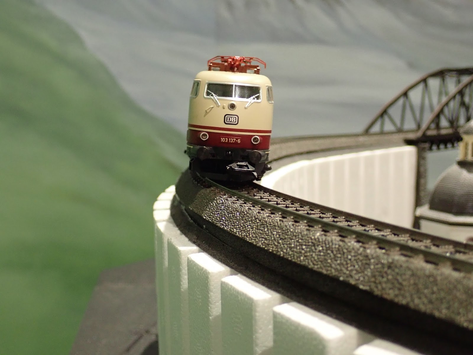
2) Canting of Curved Track:  

Interesting that the cant on some curves required only about 3mm of elevation, and others, like the curve in this picture, required a 5 mm elevation!!!!  The affect is dramatic for a train "comin' round the bend" !!!!  


3) Ballasting and Weathering Marklin C track: 

a) Weathering the track: 

 I've experimented with various colors and methods to weather the rails and the track beds.  Air brushing is simple and easy.  U Tube has many videos with an wide assortment of methods to achieve realistic weathering.   I've also studied many pix of European trains, specifically the appearance of the rails, sleepers, and the middle portions of the tracks.  In sum, the " natural weathering" created by usage, is subtle.....it's "there", but then again, "it's not there"....in other words the weathering of the track does NOT attract the eye away from the main point of interest: The Train! 

Obviously,  some track lanes which experience less traffic are more "rusty", and tracks in geographic areas with abundant rainfall , also have a more overall "rusty" appearance,  but for the most part the rails in Europe do not seem to have that stark rusty appearance.  ( Photographic axiom: light, and  contrasty colors attract the eye.") 

So......what colors to use?  I chose "Rail Brown", and "Grimy Black" colors from Badger paints. 

 b) Ballasting Marklin C track:

Interesting experiment here!  Used medium WS gray ballast for now....will probably "tone down" the color with the air brush using a little overspray of  "grimy black"....

Contact medium:  I've read that using white glue will significantly harden the ballast and negate the sound inhibiting properties of foam or whatever folks use to minimize train noise transmission to the underlying benchwork!!!!  I did use white glue on a small portion of my last layout and the noise transmission was really annoying. 

So.....the recommendation was either "Scenic Glue" from WS, or "Mod Podge" ....diluted 1:4.
Results: the ballast seems somewhat "soft" compared to the rock hard results of the white glue.  Will run trains today to test the noise transmission on this small portion of track. 

Below are a couple of links which helped me with weathering and ballasting. .....

Ballasting Marklin C track: 
https://www.youtube.com/watch?v=4s1OiQJ1kws  ( note the modeler's weathering techniques ) 

Weathering Track:
https://www.youtube.com/watch?v=7xGulPMelIc  ( beautiful air brush technique) 


This pic not great....but with a little "grimy black" air brush color to tone down the eye catching gray ballast, the results should be much more appealing .....we shall see...


I guess that's all for now.  Please comment with your observations, alternative methods, and suggestions....we all share and learn from each other. 

In the meantime, have a very Merry Christmas, and God's abundant blessings to all......

alan


Thursday 30 November 2017

First Stages of Powering Main Level of Layout


Bus # 5 


Main Level of Layout where the helix at the top of the pic feeds elevated blue track to main level and receives trains exiting the main level to return to the staging yards. 

Bus # 5:  Power added to yellow part of track which includes the lower most located lane ( in the pic)  to the passenger terminal, part of the elevated track to the bridge at the lowest part of the pic, and a portion of the commercial freight yards.  

One transformer powers this isolated segment of track. 

Red dots: Insulation points
Black dots: Power...feeder wires to distribution strip
Dark Green Marks: Contact track to the S88 

Why one transformer to this area?  At least one rail bus will occupy the passenger lane, perhaps two. At least two working steam locos will be in this maintenance area, and then there will be transiting freight trains.  So given that power draw, one transformer was selected. 

Contact tracks will be added to both the entry and exit of each isolated "block". 

Recommendation:  check each block or section of track powered by a single transformer to make certain that the track insulators are working properly.  I always test the insulators to make certain that current does not "bleed" into the next block section.  I actually did find a "bleed" into another section of track. The insulators were placed properly...I thought...so I replaced them with another set...problem solved. 

----------------------------------------------------------------

Review of Contact Tracks:

"Business" end of contact track:  blue wire soldered to "O" terminal and insulator placed on that side.


 Adjacent C track with the insulator on the same side as the soldered contact to the S88
Used a Dremel to cut the "O" connection on each end of the C track contact track to isolate the outer rail.


------------------------------------------------------------------------

Find the "short"....!!!

Ok, so now we have a short in the layout.  We have 5 transformers connected to the layout, each powering a segment of track, and several turn outs.  How to find the section of the layout to begin locating  the electrical short? 

IF the transformer plugs are numbered according to their powered bus sections, we can isolate the area in question.  Unplug all the transformers except those powering the CS's....I have a transformer for each CS ( not connected to track) .   

With the system booted up, plug in the Bus transformers one at a time till the layout shorts out with the last one plugged in.....then search that section for the culprit.  In my case I found that a feeder wire paddle had detached from the C track.  I soldered that feeder wire!!!  ( must have happened with taking apart track to add the contact track)  


On to the next section.........Auf Wiedersehen....


Thursday 9 November 2017

Computerization of Layout?

Hello from Los Osos, Calif.

Sorry for being incommunicado....visiting grandkids in California for a month, will return in the Thanksgiving time frame....then more progress on the layout and subsequent blog entries.

This separation from my layout has provided a fortuitous opportunity to "step back" and evaluate options regarding how to proceed with layout wiring and train control.

Fortunately I have been presented with distinct opportunities to speak at length ( email) with some august members of  ETE ( European Train Enthusiasts) who represent a vast reservoir of experience and passion for the hobby.

The Marklin-users.net Community remains an constant as well as interesting cache of information and experience...much to learn from this forum.

Options: 

1) Proceed with the traditional approach:  wiring the layout with expensive Marklin signals,  CS block regulation,  programming the Central Station accordingly,  installing the 72442 Marklin braking modules ( or the VM equivalent), etc.

2) Computerize the layout and allow the more sophisticated software programs currently available to regulate the layout with the options of manual override.

Traditional Approach: 

Pros: 
1) Plethora of printed information created by the "Marklin Dudes" available in the Marklin Digital Newsletters.
2) Marklin Dudes represent and incredible source of advice and experience if one were to encounter difficulties.
3) Satisfaction of wiring the layout and all its intricacies! -- ( not completely convinced about that one!! )

Cons:
1) Frustrations encountered with the learning curves and working out the "bugs" of wiring difficulties.
2) Time--and more time-- and effort to wire the layout.
3) Cost:  Marklin signals are expensive,( but beautiful and efficient, even more so than in the past. Would need lots of these signals.
4) Learning curves with programming the CS.
5) Potential problems with running trains bi-directionally....thru the signaled sections.


 Computerization of Layout:

Pros:
1) More expeditious completion of the process to "wire" and achieve a functioning layout. (Then can spend more time on my favorite aspects of the hobby: Scenery!!! )
2) More control of train movement without the threat of "accidents"--especially counter-directional competing with "through" traffic.
3) More options for moving trains around the layout with less hassle.
4) Movement of trains bi-directionally without complicated contact track and signal programming-wiring  / CS programming.
5) Save $$$$ by buying signals which do not require the sophistication or control of Marklin signals. The less expensive signals have no regulatory control, only "eye candy" for the observer. The computer does all the work.
6) Some software programs have a steep learning curve...others...not so much.
7) Incredible number of UTube learning videos available for the "TrainController *TM) software.


Cons:

1) Cost: Will have to buy a PC ( I am currently an "Apple guy") ...Costco a good resource, etc.
2) Cost: Will have to buy the TrainController *TM software, install and program. ( i.e. learning curve)

The cost of the PC and software just about offsets the cost of additional modules such as the 72442, Marklin signals--of which I will need many to make the layout appear as "ideal" as possible. ...see latest Marklin new mags.

So the bottom line:  save time and frustration crawling under the layout and wiring the "traditional approach" vs. computerization.

One of my ETE friends had already wired his layout in the traditional manner, and subsequently removed all that work and invested in computerization.  I believe he smiles a lot! I can't imagine tearing out all that wiring and those modules, but he did so.

Thought provoking, no?

-------------------------------------------------------------------------------------------------------------

Some pix taken before we left for Calif to visit the grandkids....below is a mockup of potential steam repair facility--yard ....not certain how to proceed...do not have room for the equipment from last layout and that very detailed steam yard.


Modified the ascending ramps the the "old city " and cathedral area....looks better. Will need some water effects and bridges in there somewhere. Obviously will need to place the foam boards for proper elevation.


 Testing locations for city buildings and bridges.  Could be an interesting scene. ...tram? Possibly.


 More test locations of existing buildings...and control towers.


 Well, I'll sign off for now.  If anyone wishes to offer advice please PM me at amfisher102@mac.com.

Thanks for reading....Hope your Thanksgiving and Christmas Seasons are joyful and blessed for you and your families.

alan


Sunday 8 October 2017

Track, Foam padding, Elevated track, and bridges.

Time for a brief update on the layout.

Main Level birch plywood replaced over the staging yards, once they were wired, contact tracks and stop tracks installed,  AND the CS programmed to automate the yards! The main line through the yards was not automated.


The ramps from the helix proper to the main level of the layout had to be replaced with wider ramps and the Noch viaducts.  Below shows the "up" ramp to the main level which enters the main layout 4" above grade.  A lot of adjustments with pitch, incline and precise positioning during installation. Hot glued the structures to the base "plate" secured in place with screws and thus removable for scenery details to be added later.  Noch viaducts incredibly easy to work with.  Ask Walter!!! ;-) 


From the helix vantage point, looking across "up" viaduct to main level. The "exit" viaduct from the main level return to the helix crosses under the "up" ramp.  "Base" plate for the "exit" viaduct is closest to the helix on proximal side of the "up" viaduct. 


Better view of the "up" viaduct and the base plate for the main level "exit" viaduct. 


Exit viaduct installed on removable base plate.  Helix ramp on the left of pic. 


Both viaducts installed. Removable for scenery placement. Higher viaduct is "entry" from helix to main level, and lower viaduct leaves main level and enters helix down ramps.


Another view. Happy with the result. 


Time to add Woodland Scenics Super Sheets...5mm ( 3/16") foam padding for sound reduction. On my last layout the foam insulation worked very well for 14+ years before we moved.  On the last layout, I used mostly the "track foam" under the C track, but I continually had to deal with the hassle of the 3/16" difference in Ht for building placement, centenary masts, etc...a real pain in the neck. So here I decided to use the foam on the whole layout.  Not cheap, but a real time saver. 
Four passenger lanes to the terminal on the Rt, and the industrial areas / freight by pass on the Lt. 


Beginning to add the WS risers. This method is easier than cutting ramps and installing them. Some of us just do not have the equipment of skill to do so. 


Adding bridges and risers. The raised track will divide the layout into a commercial / freight traffic side from the passenger traffic side of the layout.  Fascia board on the very edges of the layout will also add peripheral elevation and  depth.  I tried my utmost to avoid numerous tunnels because watching the trains dance in and among terrain features is more entertaining than tunnels. Also requiring the viewer to "peer over" the edge of the layout adds depth and interest.  On my last layout I really aced that objective. http://goo.gl/LebzJ4  Not enough time or available room to do the same here. 


Apologize for the appearance of the track. Much of the salvaged track from my last layout was in winter scenery so it has a white cast...which will be airbrushed away ( weathered)  after  adding ballast and catenary. 


Risers and additional bridges installed. This is the "industrial" side of the layout.  Arched bridges in center welcome vehicular traffic from the city. ...whenever the streets "magically" appear!  ;-)


Visual test!!! Can you see the difference ???? Note the cant of the passenger car just below--mounted on track foam.  

 Spacer inserted on outer edge to provide prototypical elevation to the outer edge of the track curves. 


 Level on "uncanted" track. 


With canting spacer. 


 Viaducts and bridges. First signal for the block system of auto regulation. 


This bridge was a real challenge! Positioning pillars was difficult to establish realism.  Could not use the common cement pillars here, so used the Noch pillars.


Overview. Elevated track ( with passing lane)  continues down the left edge of the picture, then crosses over the main line to the descent ramp onto main level.


Trains leaving the passenger terminal traveling to the "Old City" and the cathedral, will bypass the main line ( counter main traffic)  and enter an elevated ascent track to the elevated plateau ( not yet installed with pink foam) where we will find the not only a cathedral and the "old walled city", but perhaps a monastery as well.  The plateau will be at least 4" above grade and the cathedral, well .... perhaps more. 


 Now....to wire the layout for power, install contact tracks, stop tracks, and signals. ....and begin to develop a strategy to weather --airbrush the track --and add some ballast...

Thank you for sharing ....if anyone has suggestions regarding weathering track ...please...shout out!  alan


Tuesday 19 September 2017

Programming the Staging Yards:


Staging Yards.  ( BTW the German alphabet has no "Y")

This is the "north bound" section of the yards, with an almost reciprocal image for the "south bound" lanes.  One passing lane and 4 "holding" lanes on each side of the staging area.

Conceptually, the plan follows thus: 
1) The passing lane ( entry / exit lane ) will not be automated.
2) The staging yards will be automated.
3) Entry into the Staging lanes will be manually controlled, not automated.  ( more below)

Stop Blocks:
Prepare a stop block at the end of each lane with M84, K84 or VM 5213.  Make certain that when the train halts it will not impinge on any other adjacent lanes.

Contact Tracks:
Much has been written about Contact Tracks. Best reference: Curtis' article in the Marklin Digital Newsletter: Vol 27, No. 2 pages 6 & 7.  Make certain that then CT's are not too long ( about one car length) otherwise the CT shortens the length of any train which can be stored on that lane.

Be careful! Contact Tracks are a trap for frustration. Some pointers:
1) Use a Dremel to cut the "ground" joints under "C" track--cleaner method.
2) Solder a single wire to the CT section. I chose "blue" wire for simplicity...to connect to the L88. NO solder on these connections to the L88!!!!
3) Keep meticulous notes! Keep meticulous notes!!!
4) In the layout mode place the CT icon on each lane and ID the contact point.
5) Frustration:  Even tho the CT's were properly soldered, and insulated on all lanes, ( I thought!) the icon on the layout panel of the CS 2 --on only ONE lane indicated occupancy when there was none! Now what?  After replacing track, and essentially rebuilding the CT area, the same occupancy indicator appeared!  Aarrrgh!  Then the "light" went on....the insulator points were on the same "ground" side of the track, but not on the proper side....switched the insulators to the other side. and hooray ...it worked.

I have not seen this mentioned in some of the other blogs I have read....just a word of caution! ;-)

Now onto programming the yards..........

Now for "fun" times!!??  The process is actually fairly straightforward IF you follow all the instructions precisely.  ( I made plenty of mistakes!)

References:  Marklin Digital Newsletter: Vol 28, No. 1; ( pages 6-12);  Vol 28, No. 2 ( pages 6-13)
Study them...a lot!

1) Make certain all the components are programmed into the "Keyboard": Turnouts, Stop Blocks and Contact Tracts
2) Make certain all the components of the layout are programed on the "Layout" section, including all  Turnouts, Stop Blocks, and Contact Tracks.
3) Programming the "Memory" section, involves "activating" ( wrench) the Memory Section while accessing the components in the Layout Section  ( not the Keyboard....much easier to use the Layout Section)

See pix below with explanation:

Goals: 
a)  Have a passing "main line" lane through both sides of the staging yards, with 4 storage lanes on each side of the yard.
b) This allows "favorite" trains to pass thru the staging yards and return via the helix to the main level of the layout.
c) Option of "manually" operating a turnout, allowing a train to enter the staging yards to an empty storage lane on either side of the yard.
d) Once the Turnout has been thrown allowing the train to Enter the Staging Lane ( SLn), the train passes over the Contact Track,  converting the Stop Track on the same lane to turn red...to stop, and also turns the adjacent stop track to "green", allowing that train to leave and enter the main through lane.
e) When the train Exits the contact track, the turnout through which the train entered the staging lane now turns to prevent another train from entering the same lane.

Screen shot of the Layout: one side of the staging lanes. A train has entered the lowest lane and stopped. Simultaneously, the train in the lane just above the lowest lane has left the yards, because the stop track has changed to "go", releasing that train.


2)Memory screen:
 Wrench->Note: 
Address: SLn5 ( Staging Lane 5) 
Contact: 5 
"Tr." Loco on the ENRTY or Lt side of small screen. ( Entry into the Contact Track area). 
Add ( Stop Tracks): "Stop" for Ln 5 and "Go" for Ln 6, by clicking on the specific component on the layout screen. ( only the Memory Screen is "active" for programming, not the Layout Screen. 


 Programming the "Exit" component from the Contract Track:--> Move the "Loco" icon to the right side of the little box with the pointer. Then, select the turnout from the Layout Screen. Thus when the train leaves the Contact area, the turnout throws to prevent another train from entering that same lane.


 Next step: Click on the "EXT" icon. This screen appears. The top line is the "temporary" contact line ( see Newsletter). Make certain that the appropriate contact track number is registered. e.g #5! AND the L( S88) is registered!!!!!   Close this screen. When finished programming that Memory icon, then close the window with the blue down arrow and then the green check mark. ...to save the info.


This screen shows a Loco entering the staging lane at the top of the four lower lanes. The very top lane is the "main line". The contact icon is yellow....indicating occupancy.   REMEMBER: if your Contact Track appears yellow and there is NO train on that CT, then you have your insulator points on the WRONG side of the track!  


Good luck programming your staging yards.  Full disclosure: this section drove me crazy for awhile, till I sought advice from others and re-read the Newsletters...for the ~10th + time! 
I believe that one of my biggest obstacles was the time frame involved for the Central Station to "digest" the programmed information. My "hunch" is that the processor in my older 60214 is much slower that the newer models. ( When finished programming any information, I usually allow the CS to remain "on" and "idle" for about a half hour before "saving" the information and then "quitting" the CS. 

It's most difficult not to become discouraged or frustrated. Persistence  is the key. Ask for help if needed. Some "figure it out" before others. I am writing this blog to try to help others avoid some of the frustrations that I encountered. 

Blessings....alan 


Addendum: 

Side point: I marked the insulation point on the track in the Staging Yards with a double black stripe, so if I have to return to shorten or lengthen contact blocks or stop blocks I would know immediately where the insulation points were located. 

Contact track: marked with an "X" where insulator points are located. 


Brief video showing how train passes over contact point and throws turnout to prevent another train from entering that particular staging lane. 


Friday 1 September 2017

Fisher Bahn II : Connecting the L88

Connecting the L88

For the most part connecting the L88, the first device between the CS and the S88 feedback module
network is easy following the instruction manual.


Ref:  Digital Newsletters: Vol 27: #2,   Vol 28: #1-2

Connect the L88 to the CS at the 60174 booster slot. All S88's then connect to the L88.  THEN connect the power module. 

Do not make the same mistake I made with my dual Central Stations! 

The red wire rising from the Left CS is a temporary programming wire connection to a section of track to register locos and reprogram signals. 

Problem: I mixed the connections between the "slave" and the "master" CS units and my L88 would not properly register on the master CS. ( thought I had really scoped out the correct connections!!) 

Further the checked boxes for the slave to acquire information from the master are actually located on the slave CS under the set up panel. 

In sum: The cable connecting the two CS's: the 6 pin connection is the master; the 9 pin connection is the slave.  Once properly connected, no problem with registering the L88.  

Whew...now onto the fascinating challenge of installing signals ( stop blocks), contact tracks for each staging lane, and programming the CS's so that when a train enters an empty staging lane, it released a train in an adjacent lane....should be fun when it all works out!!!! ;-) 


Fisher Bahn II Step 1: Automation of Staging Yards : Stop Blocks.


Programming Signals with the Central Station 2. 


Automation of the staging yards: Step 1:  Installation of "stop blocks"

1) The best Marlin references on the planet are the Digital Newsletters from the Marklin Digital Club!  Take a bow, Curtis Jeung, you are a hero to so many of us! 

2) Reference: Digital Newsletters, Vol #27:  No. 1-3 , and Vol # 28: No. 1-3

Because I retained 8 Marklin yard signals, 74371 / 76371, from my old layout, and because they really look cool when watching a train stop in the staging yards, I decided to wire them into the layout as an easy way to secure a stop block for each of the staging lanes. 


I happen to be one of those folks who needs specific instructions on how to wire or connect devices. 

To reprogram these signals I read the signal instructions, reviewed the newsletters, and decided to give it a shot. I had never used the CS to program signals before. (  CS = 60214- with current software: 4.2.1 ) 

Below is a concise summary: 

  • CS powered but turned OFF. 
  • Program Track: ( connected to Program Track slot of CS) 
    • Connect feeder wire paddles to track end  R / B 
    • Connect Yellow from signal to Red ( Brawa Plug set)
    • Connect Brn  from signal to Brn ( Brawa plug set) 
  • Connect "programming base" from original packaging to bottom of signal circuit board ( the cardboard panel that clips onto both sides of the circuit board) 
  • CS "ON"
  • Keyboard Mode: Select the Keyboard panel you wish to use. 
    • Choose the slot for the signal 
    • "Wrench" ->highlight the keyboard icon
      • Set address: e.g S 5
      • Select Icon: e.g. Sh0, Sh1 ( stop, go) 
      • red / white lights on signal should flash alternately. 
      • Close out programming mode. 
  • Remove programming base. 
  • Check signal. 
  • Your signal is now reprogrammed! 
Now, install them!  ;-) 

Addendum:  19 Sept:  Decided to save the signals for the most visible part of the layout, and not use them for the staging yards. Choices for control devices:  VM 5213,  M84, K84. All work quite well and are easy to install and program on the keyboard.  Enter the information onto the "layout" portion of the CS.  ( Marklin Digital Newsletter resource is invaluable!!!! )

Wiring for the Stop Blocks: 
1) Used "green" wire from the middle of the stop block to connect to the control module--fitting because the wire inserts into the "green" port!
2) Red wire to the outside of the stop block.
3) The group of staging lanes were insulated from the main line as expected.  Had to install another feeder wire to the "down" side of the stop block grouping for power.


Fisher Bahn II--Wiring Staging Yards,


Wiring Staging Yards. 

Keep thy wiring neat!

 I've read many posts about wiring, some are absolutely ingenious! I chose to follow the older system, using a larger caliber wire from the Transformer / Booster  combo to the distribution panels. Then connecting the feeder wires after soldering the tips, of course. 

FWIW I have been using a butane soldering iron which works well. Why, you ask?  


Two reasons:
1) While moving around under my last layout, and using a traditionally plug-in soldering iron,  I happened to accidentally place the palm of my hand on the soldering iron!!! Big ouch! Now when I am done with the short soldering chores, such as wire tips, I turn off the iron and place it in an old teflon coated pie pan and push it away!
2) While using the same traditional wire fed soldering iron, the dumb thing fell off its cradle and burned the rug! Ugly! My bad! 

------------------------------------

This time, I am meticulous to make certain that my red / brown wire junction plugs are not adjacent to each other but safely offset.   On my old layout,  two plugs contacted each other and shorted out the entire layout....what a mess to diagnose and finally resolve the issue!  Zip tags are an easy method to identify ( and record!!!) your wiring harness.  

Remember: Experience-> knowledge-> wisdom-> success.  By sharing blunders and faux pas perhaps we will spare others !  ;-)  


Previously, my wiring was almost all "overhead" secured to the underside of the lowest level of the layout.  A few scalp scars attest why this current layout's bottom level is higher than the last one! Further, I will never secure servers, etc overhead....especially with soldering...too much danger of solder accidents.


Now, I secure wiring harnessed to a vertical plane. This particular panel is screwed to a support leg of the layout.  Note that each bus is labeled with the Zip tags. 
Bus #1: Through lanes
Bus # 2: "South bound lanes
Bus #3 North bound lanes. 

<- N,  S->

Red dots: insulating points
Black dots: Feeder wires 
Yellow lane: Main through route. 

Keep meticulous notes !!!!